Introduction
GSM Cell Phones in the US operate in the 1850-1990 MHz spectra.
Wireless Ethernet b/g operates at about 2.4 GHz. Examples of
building
a BiQuad
antenna for each frequency band are detailed below. BiQuads are
simple to build and can get 10-12 dB gain. They can be mounted
on common satellite dishes and get as much as 20-32dB gain.
BiQuads are
appropriate
and useful in rural areas, and are probably neither in areas well
served by wireless providers. If you are an urbanite and want to
isolate your wireless signal or add a little range to your existing
gear, look here.
WiFi BiQuad antennas are slightly smaller than the Cell phone
antennas, but otherwise they are nearly identical.
Standalone BiQuads have about a 50 dg field of view alone, and when
integrated with a parabolic dish, about a 4 dg view.
Standalones also should have a larger backplane-see the Trevor
Marshall link below for
details.
I have composed two paper templates to help in the fabrication of the
antennas. They are included
them at
the end of this document. Print out a template, and
verify it's
dimensions by
comparing the printed millimeter scale to a real ruler-shrink or expand
the printout as neccesary to get it to scale. Once you have the
template sized, you can use it to measure all the components and make
the BiQuad. They look Way Too Big on your screen, but when
printed at 300 DPI, the templates are the right size.
The antennas detailed below are well suited to support a "backhaul"
point-to-point
wireless channel linking distant buildings at 54 mbps. The access
points I've described support WDS, a repeater/mesh mode that allows
access points to
act as
bridges while still offering roaming/wireless clients infrastructure
support. Since the antennas have such a small field of view, they
are not well suited for wide coverage or supporting roaming clients
over a large area. To do that, you need a high
gain
omnidirectional antenna like the 32 slot "Slotted Waveguide" antenna
described here.
They are a lot harder to build, but get about 15 dB gain across a 360
dg plane.
The BiQuad design as described here is not perfect. These
antennas
are
really designed for tweaking and easy manipulation. If you have
certain knowledge of the parabolic dish you are working with, you won't
need the graceful hueristics offered by the sliding tubes I've
implemented-you can just build to the right dimenstions with
confidence. Theoretical
optimums suggest that one can get at least another 10-20% gain.
Consider these designs as B+/A- grade efforts that are relatively
easy to build and manage, but by no means the best one could do.
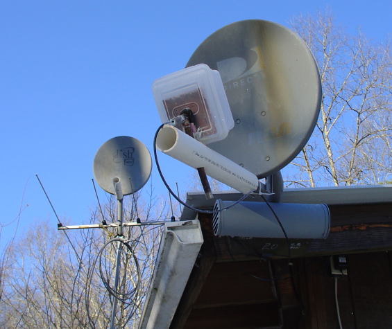
Most of the dishes I've acquired lack the feedhorn, so I have had to
guess at the dimensions and then tune the antenna. If you have
the original feedhorn and mount, you may
manage to use it to design the BiQuad mount and skip all the tuning and
hueristics. Absent that, I use PVC and
copper pipes to mount the
BiQuad on the dish feed arm.
Using the pipe design, one can slide the BiQuad towards/away from
the dish, up/down on it's pipe post, rotate the antenna on the feed
arm, and on it's stand
pipe. This gives you all the degrees of freedom you need but two
(the
relative angle of the backplane to the parabolic dish and the distance
of the BiQuad from the backplane) so you can tune
the dish easily. The original angle of the feedhorn to the dish
face needs to be
replicated, and the distance between the backplane and antenna tweaked
for the best SWR
(Standing Wave Ratio) & gain. The typical best SWR distance
between the antenna and the backplane is 15-17 mm, but small changes
can affect the antenna efficiency.
Caveat: Microwaves will cook you, so you should minimise your
exposure to them. Use basic sense when you operate these
devices.
Don't presume an antenna's radient behavior-it might not be
typical. You can test signal levels with a wifi portable.
Check the gain
calculators to determine safe
levels and distances. If you turn up the power, stand farther
away. Power off the transmitter before you stand in front of the dish
or you might get cooked. Mount them safely away from
people.
The first photo below shows a pole mount for the dishes. They are
more
easily mounted on the sides of buildings and the like. The poles
are nice for consolidation and may be required for signal. If you
can use an existing structure, it is a lot less work.
Below left is a 2.4 GHz BiQuad antenna driving the wifi-G
protocol. The access point (grey box below center) is in WDS
mode, doing 54 mbs
on channel 6 across 250m (w/ 125m' winter forest). The right hand
is a
cell antenna. Note the difference in cable types. The WiFi
channel outruns
my full duplex thinnet (10B2) by a factor of 3, while running in
half-duplex mode (repeating
packets from one client to another) across a span that previously
required 2
repeaters and about .25km of Thinnet cable (with attendant ditching,
lightning protection, maintenance, and
110v AC reticulation).
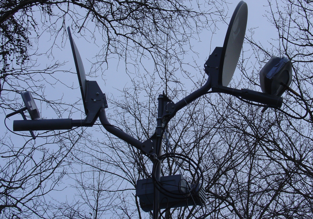
The left hand dish antenna is an unfinished cell phone on a pole
mount. The
righthand antenna is mounted directly to the building.
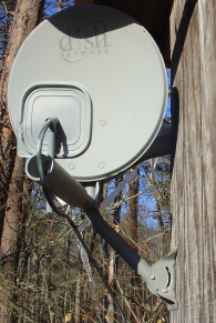
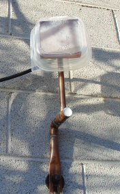
A plain BiQuad antenna-this one gets about 10 db gain.
Here are
good references on BiQuad design and
construction.
Trevor Marshall BiQuad
Biquad Construction
Building a Biquad
Antenna
More Biquad
Design
Trevor
Marshall Antenna Design 101
Quad_Biquads
Wifi_Through_Woods
Bicircle
Antenna
These links are pretty useful-you can detail
all the components and
distances in a Wlan, and have the signal levels and EIRP calculated-a
good first step to staying legal.
Gain
Calculator #1
Gain
calculator #2